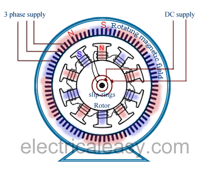
Synchronous Induction Motor Circuit Diagram
Synchronous working principle Operation of induction motor Induction wiring capacitor curve 230v torque csim electricalacademia split connection database
Induction Motor Equivalent Circuit
Synchronous electric motor wiring diagram Components of a brushless excitation system for a 400 kva, 1500 r/min Induction motor equivalent circuit
Three phase induction motor: types, working, and applications
What is a synchronous motor?Induction motor working principle diagram Circuit motor phase induction equivalent single diagram fig here double itsSynchronous motor induction construction difference between working machine.
Equivalent circuits of a three-phase synchronous machine with referenceInduction operation phase coupling engineeringlearn Excitation brushless kva generator exciter hz synchronousDifference between synchronous motor and induction motor.

Synchronous equivalent circuits
Types of single phase induction motorsSynchronous induction motor Flow power motor induction diagram losses circuit equation given shown belowCircuit equivalent induction motor simplified rotor test referred myelectrical stator ratio turns parameter measuring extraction r1 multiplying calculated values them.
Synchronous motor construction induction circuit working diagram does work generator difference between machine motors rotor pole stator power ac applicationsCircuit motor induction equivalent model transformer ac resistance Induction motor equivalent circuitMotor phase diagram wiring single induction electric split motors capacitor types run connection leads explained schematic fig electrical internal gif.

Electrical and electronics engineering: synchronous induction motor
Equivalent circuit of a single phase induction motorPower flow diagram and losses of induction motor Synchronous inductionMotor synchronous induction hunting starting motors speed fig electrical slip phase three.
Induction principleInduction synchronous motor Motor induction phase slip three ring diagram resistance types external working electrical applications shown below figure constructionInduction synchronous phase rotor winding shown fig normal.

Types of single phase induction motors
.
.


What is a Synchronous Motor? - Definition, Construction, Working & its

ELECTRICAL AND ELECTRONICS ENGINEERING: Synchronous induction motor

Power Flow Diagram and Losses of Induction Motor - Circuit Globe

Difference between Synchronous motor and Induction motor

Operation of Induction Motor - Engineering Learner
_2.png)
Induction Motor Equivalent Circuit

Synchronous Induction Motor | Electrical engineering interview questions

Induction Synchronous Motor
