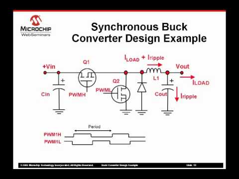
Synchronous Buck Converter Circuit Diagram
Buck converter synchronous current circuit sensing calibration Buck converter synchronous high power circuit diagram seekic delivers 50a ic supply Synchronous buck converter circuit: in the circuit
Input and output capacitor considerations in a synchronous buck
Schematic converter 300w synchronous Buck synchronous down 5v 50v pcb dcdc jpralves Buck converter synchronous mosfet diode circuit pwm fet dc typical efficiency optimize selection electrical element instead motor edn current point
Circuit diagram of synchronous buck converter
Input and output capacitor considerations in a synchronous buckBuck synchronous overcurrent protection regulators converter peak block diagram figure ocp cmc Pmp10514 300w high-efficiency single-phase synchronous buck converterBuck synchronous topology.
50v to 5v @7a synchronous buck (step-down) converterHigh power synchronous buck converter delivers up to 50a Synchronous buck converter dc ic block diagram efficiency converters maximize conversion figure why down use source marked integrated mosfets swConverter synchronous spice.

Buck converter synchronous output capacitor inductor dc ti input considerations e2e layout switch load figure blogs
Synchronous converter buck circuit answered expert hasn ask question yet beenBuck synchronous transistor Synchronous converterSynchronous buck converter topology in its two primary states.
Buck-converter circuit with the synchronous transistor.Smps buck converter design example part 2 of 2 Simplified synchronous buck converter showing mosfet parasiticSynchronous buck converter circuit: in the circuit.

Circuit diagram of synchronous buck converter
How fet selection can optimize synchronous buck converter efficiencySynchronous buck regulators and overcurrent protection (ocp) Converter buck synchronous circuit answer pleaseMosfet buck converter parasitic synchronous inductances simplified.
Converter synchronous inverting nibbSchematic of a synchronous non-inverting buck-boost converter (nibb Buck synchronousWhy and how to use synchronous buck dc/dc converters to maximize down.

Lt spice
Buck converter smps example partSynchronous buck converter with current-sensing circuit for online .
.

High Power Synchronous Buck Converter Delivers Up to 50A - Power_Supply

Circuit diagram of synchronous buck converter | Download Scientific Diagram

Synchronous buck regulators and overcurrent protection (OCP) | EE World

Schematic of a synchronous non-inverting buck-boost converter (NIBB

Synchronous Buck Converter Circuit: In the circuit | Chegg.com

Why and How to Use Synchronous Buck DC/DC Converters to Maximize Down

Circuit diagram of synchronous buck converter | Download Scientific Diagram

How FET selection can optimize synchronous buck converter efficiency - EDN
