Synchronous Bcd Counter Circuit Diagram
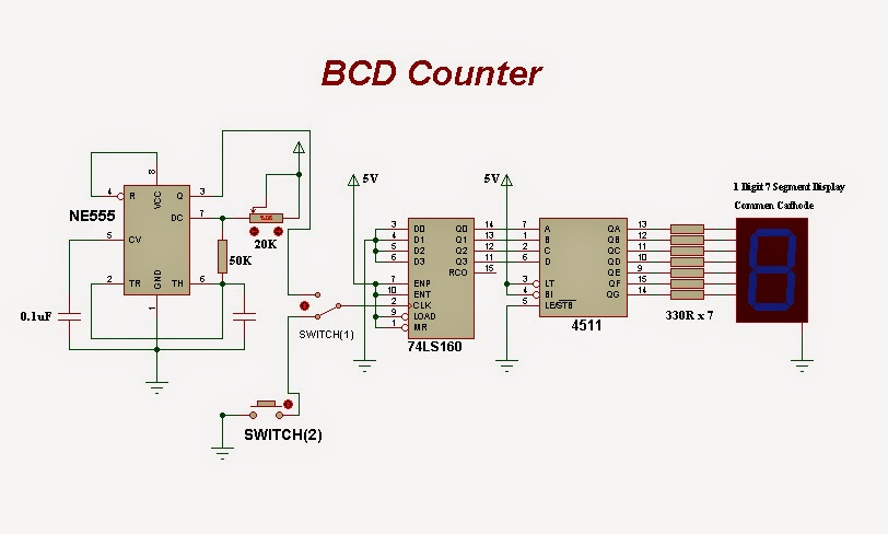
Synchronous flop flops Counters in digital logic Future dreams: bcd counter circuit
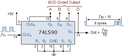
BCD Counter : Pin Diagram, Circuit, Working and Its Applications
Counter bcd flip using synchronous flops digital schematic applications types working given below Bcd counter : pin diagram, circuit, working and its applications Synchronous timing counters asynchronous logic 4bit geeksforgeeks iitr
Bcd jk binary flops
17. the bcd (mod10) synchronous up counter circuit constructed with dCircuit bcd counter diagram dreams future Synchronous bcd mod10 flops constructed murat figVirtual labs.
Counter bcd circuit 74ls90 divide count synchronous mod using binary decade down bit counters asynchronous digital connect which typeSynchronous timing counters asynchronous electronics circuit logic 4bit geeksforgeeks Digital synchronous counterWhat is synchronous counter? definition, circuit and operation of.

Synchronous counter and the 4-bit synchronous counter
.
.


17. The BCD (MOD10) synchronous up counter circuit constructed with D

Future Dreams: BCD Counter Circuit

Digital Synchronous Counter - Types, Working & Applications

What is Synchronous Counter? Definition, Circuit and Operation of

Virtual Labs

BCD Counter : Pin Diagram, Circuit, Working and Its Applications
